Abstract
Registers and Counters are multi-bit sequential logic structures constructed by grouping D Flip-Flops under a shared clock signal. A Basic Register stores an -bit data word in parallel. A Shift Register connects flip-flops serially, propagating data bits sequentially per clock cycle. Connecting combinational decoding logic to shift register outputs forms a Pattern Recognizer (Sequence Detector). Adding 4:1 multiplexers to each bit slice creates a Universal Shift Register capable of holding state, shifting left/right, or loading parallel inputs. Counters step through a predetermined sequence of binary patterns, repeating after a fixed modulus cycle count.
Basic Multi-Bit Registers
A Register is an array of flip-flops sharing a common clock signal that stores an -bit binary word simultaneously.
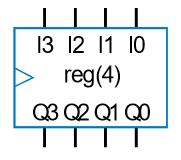
4-Bit Register Symbol
Parallel Architecture
Each bit of an incoming multi-bit bus () is connected directly to the data input of an individual D Flip-Flop. On the active clock transition, all input bits are captured in parallel to update outputs ().
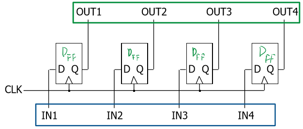
Internal Schematic of a 4-Bit Register using Parallel D Flip-Flops
Shift Registers
A Shift Register connects flip-flops in series such that the output of stage feeds the input of stage ().
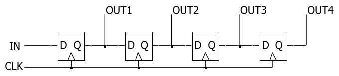
4-Bit Serial Shift Register Schematic
Serial Bit Propagation
Because edge-triggered D Flip-Flops sample inputs strictly on clock transitions, a single input bit propagates rightward by exactly one stage per clock cycle.
Worked Example: Serial Propagation
Feeding the bit stream 0110111 (inserted right-to-left) into an initially zeroed 4-bit shift register ():
Pattern Recognizers (Sequence Detectors)
A Pattern Recognizer combines a shift register with combinational output decoding logic to detect when a specific sequence of binary bits has been received across consecutive clock cycles.
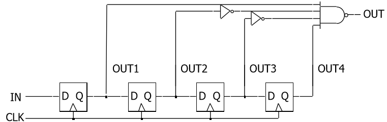
Pattern Recognizer Circuit Detecting Target Sequence
Logic Decoding Function
The example circuit monitors four parallel tap points (). When the captured bit pattern matches 1001 (), the NAND decoding gate asserts an active-low flag:
Universal Shift Registers
A Universal Shift Register combines multiple register modes—holding data, shifting right, shifting left, and parallel loading—into a single integrated module governed by select lines () and a clear control.
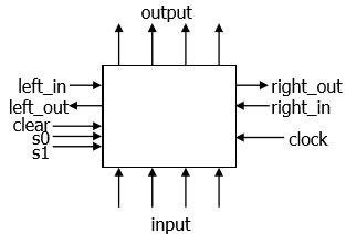
4-Bit Universal Shift Register Block Symbol
Mode Control Selection Table
| Clear | New State Output () | Operational Mode Description | ||
|---|---|---|---|---|
| Clear: Asynchronously or synchronously resets register to 0. | ||||
| Hold: Retains current value (No change). | ||||
| Shift Right: Passes value from flip-flop to the left (serial in right). | ||||
| Shift Left: Passes value from flip-flop to the right (serial in left). | ||||
| Parallel Load: Loads external input bus (). |
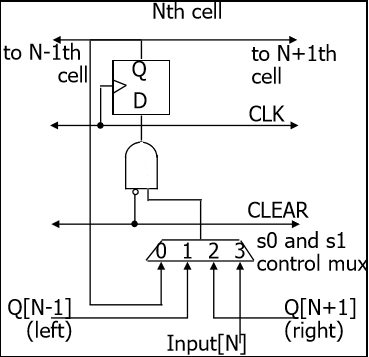
Internal Bit-Slice Logic showing 4:1 Multiplexer driving D Flip-Flop Input
Counters
A Counter is a specialized sequential state machine that cycles through a predefined sequence of binary states upon receiving clock pulses.
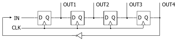
Synchronous Sequence Counter Schematic
State Sequence Iteration
Counters repeat their fixed state pattern after completing clock cycles (where is the modulus of the counter).
Worked 8-State Cycle Example
Starting from initial pattern , the counter steps through eight unique states before recycling back to the initial state: