Overview
Register-Transfer Level (RTL) Design is the blueprint methodology for structuring complex digital systems by partitioning hardware into a Datapath (executing multi-bit data transformations) and a Controller (managing sequence execution via single-bit control logic). By elevating abstraction through High-Level State Machines (HLSMs), RTL design bridges software algorithm specifications and gate-level hardware implementations while managing critical path timing boundaries across system modules.
1. Datapath & Controller Architecture
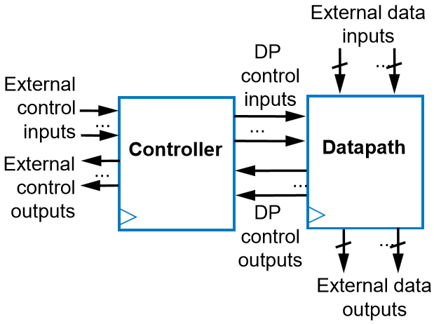
RTL divides sequential systems into two specialized functional units:
- Datapath: The operational muscle containing storage registers and arithmetic-logic components (Adders, Multipliers, Comparators, ALUs). Handles multi-bit data operations (-bit, -bit, -bit words).
- Controller: The sequencing brain implemented as a classical Finite State Machine (FSM). Receives status feedback from the datapath and external inputs to drive single-bit register load, clear, and selection lines.
2. The 4-Step RTL Synthesis Process
Synthesizing a behavioral model into gate-level hardware follows a systematic 4-step pipeline:
| Step | Action | Operational Scope | Description |
|---|---|---|---|
| 1 | Define the HLSM | High-Level Behavior | Capture system behavior as a High-Level State Machine (HLSM) using states, transitions, local multi-bit variables, and complex arithmetic operations. |
| 2 | Create the Datapath | Multi-Bit Hardware | Instantiate multi-bit registers, adders, comparators, ALUs, and multiplexers required to carry out all datapath computations defined in the HLSM. |
| 3 | Connect Datapath to Controller | System Interface | Map status evaluation signals (e.g., comparator outputs) from datapath to controller, and route single-bit control signals (load, clear, select) from controller to datapath registers. |
| 4 | Implement the FSM | Single-Bit Control Logic | Convert the HLSM into a classical Controller FSM by replacing all complex data operations with assertions of single-bit binary control signals. |
3. RTL Critical Path & Timing Analysis
In complex RTL systems, the maximum system clock frequency () is strictly constrained by the single longest register-to-register propagation path (Critical Path).
flowchart LR
	n1[Launching Register] -- Combinational Logic Delay --> n2[Receiving Register]
Potential Critical Path Locations
To prevent setup time violations (), timing verification must evaluate all potential long paths across the entire circuit:
- Internal Datapath Paths: Deep arithmetic cascades (e.g., array multipliers or long ripple-carry adder chains prior to register capture).
- Datapath-to-FSM Paths: Multi-bit comparator evaluations in the datapath generating status flags that feed directly into controller next-state decision logic.
- FSM-to-Datapath Paths: Controller next-state state decoding logic generating control signals (
load_enable,mux_select) that propagate into datapath multiplexers before register clock inputs. - Internal Controller Paths: Complex Boolean excitation logic driving next-state state transitions within the controller’s internal state register.
Submodule Notes
-
High Level State Machines
Behavioral state machine modeling, multi-bit local variable storage, complex arithmetic conditions, HLSM notation conventions, and classical FSM comparison. -
RTL Design Process
Step-by-step conversion of HLSM specifications into hardware, complete soda dispenser walkthrough, C-code behavioral synthesis (HLS), and microprocessor performance benchmarking. -
Data-Dominant RTL Design & FIR Filters
Data-dominant vs. control-dominant architectural trade-offs, finite impulse response (FIR) filter design, logarithmic adder trees, and spatial hardware parallelism vs. software execution.