Abstract
Digital systems are broadly categorized as either Control-Dominant or Data-Dominant. Control-dominant systems prioritize complex decision logic with simple datapaths (e.g., traffic light controllers), whereas data-dominant systems feature extensive, highly parallel datapaths managed by minimal control logic (e.g., Digital Signal Processors, FIR Filters). Implementing a Finite Impulse Response (FIR) Filter in custom hardware demonstrates how data-dominant RTL designs achieve orders-of-magnitude performance speedups over software by processing wide array operations in parallel along logarithmic adder trees.
Architectural Classification: Control-Dominant vs. Data-Dominant
RTL designs balance control complexity against datapath computation density depending on the target application:
| Attribute | Control-Dominant Design | Data-Dominant Design |
|---|---|---|
| Controller Complexity | High: Complex state transition diagrams, many branching conditions. | Low: Minimal state count, often simple iterative loops or single-state control. |
| Datapath Complexity | Low: Simple registers, basic gates, or minimal arithmetic operations. | High: Extensive register chains, parallel multipliers, adders, and accumulators. |
| Primary Bottleneck | Decision logic latency & state decoding overhead. | Data propagation delay through deep arithmetic operators (Critical Path). |
| Typical Examples | CPU Control Units, Protocol Handshakers, Traffic Controllers. | Digital Signal Processors (DSP), FIR Filters, Video/Audio Codecs, Neural Net Accelerators. |
Case Study: Finite Impulse Response (FIR) Filter
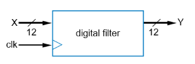
A Finite Impulse Response (FIR) Filter transforms an input digital stream into a filtered output stream by computing a configurable weighted sum of present and past input samples.
flowchart LR
    X["x(t)"] --> C0["c₀"]
    X --> D1["z⁻¹"]

    D1 --> C1["c₁"]
    D1 --> D2["z⁻¹"]

    D2 --> C2["c₂"]

    C0 --> A1["+"]
    C1 --> A1

    A1 --> A2["+"]
    C2 --> A2

    A2 --> Y["y(t)"]
Mathematical Definition
For an -tap FIR filter, the transfer function is expressed as:
3-Tap FIR Filter Equation
- Filter Taps (): The number of past input samples preserved in the delay chain.
- Filter Coefficients (): User-configurable constants that define the frequency response (e.g., low-pass, high-pass, or band-pass filtering).
- Small : Minimal delay/filtering.
- Large : Strong noise attenuation, sharper cutoff frequencies, but higher hardware resource usage.
Simple Moving Average Filtering Effect
RTL Design Pipeline for a 3-Tap FIR Filter
Step 1: Capture Behavior (HLSM)
Because the datapath processes samples continuously on every clock tick, the controller HLSM requires minimal control states.
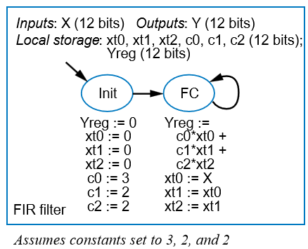
High-Level State Machine (HLSM) for FIR Filter Control
Step 2: Datapath Construction
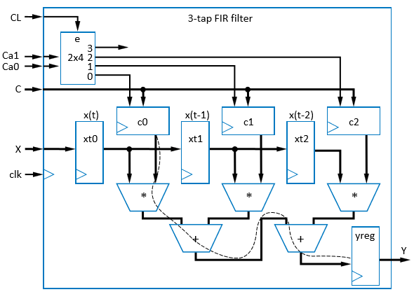
To execute , the datapath integrates:
- Sample Delay Chain: A cascaded shift register chain () storing incoming samples .
- Coefficient Registers: Storage registers for constants (with write-enable logic for configuration).
- Parallel Multipliers: Three array multipliers computing concurrently.
- Adder Tree: Combinational adder stages summing the partial products into output .
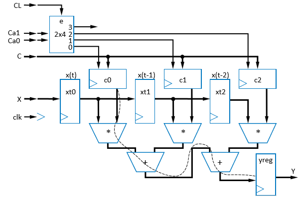
3-Tap FIR Filter Datapath Architecture
Step 3 & 4: Controller Connection & FSM Synthesis
The simple controller asserts load/clear lines to configure coefficients and manage sample propagation.
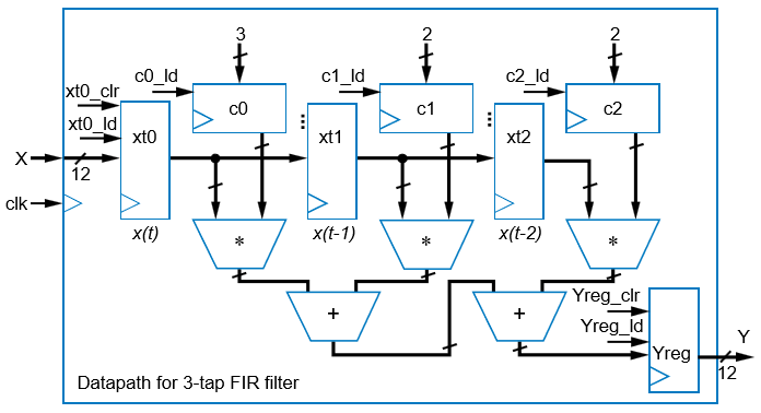
Interfacing Datapath with Minimal Controller Block
Hardware (RTL Circuit) vs. Software Performance Analysis
Evaluating a 100-tap FIR filter demonstrates the profound performance advantage of hardware spatial parallelism over software temporal execution.
Critical Path through a 100-Tap FIR Filter Hardware Adder Tree
Gate-Delay Model Assumptions
- Adder Delay: gate delays per addition.
- Multiplier Delay: gate delays per multiplication.
- Software Instruction Delay: gate delays per instruction execution cycle.
Critical Path & Performance Breakdown
1. Hardware RTL Implementation (Parallel Spatial Processing)
In hardware, all multiplications execute concurrently in parallel ( gate delays). The resulting products are summed via a balanced binary adder tree of depth adder stages.
2. Software Implementation (Sequential Loop Processing)
A general-purpose processor must process the 100-tap filter sequentially inside a loop ( multiplications + additions). Assuming instructions per operation:
Performance Summary Matrix
| Metric | Software Execution (CPU) | Dedicated RTL Circuit (Data-Dominant) |
|---|---|---|
| Execution Paradigm | Sequential Iterative Loop | Parallel Spatial Hardware Datapath |
| 3-Tap Latency | Gate Delays | Gate Delays () |
| 100-Tap Latency | Gate Delays | Gate Delays () |
| Speedup (100-Tap) | (Baseline) | Faster |
Algorithmic Scaling Advantage
As the number of filter taps grows, software latency increases linearly , whereas hardware critical path latency grows logarithmically thanks to parallel adder tree structures.