Abstract
Multiplexers (Muxes) and Demultiplexers (Demuxes) are the foundational data-steering components of digital architecture. Built from Transmission Gates and Tristate Buffers (which enable high-impedance floating states for shared bus communication), a multiplexer selects one of data inputs to route to a single output based on select control lines. Beyond data steering, multiplexers function as universal logic generators. Conversely, a demultiplexer directs a single input signal to one of outputs governed by control select inputs and enable signals.
Physical Building Blocks: Transmission Gates & Tristate Buffers
Transmission Gate Switches
Because standalone nMOS switches pass s poorly and standalone pMOS switches pass s poorly, Transmission Gates (TGs) combine nMOS and pMOS transistors in parallel to pass full-rail s and s efficiently:
- When (): Switch is ON. Input is connected directly to output .
- When (): Switch is OFF. Input is disconnected from .
Tristate Buffers & Shared Busses
When a switch is OFF, the output node enters a High-Impedance () / Floating / Open state.
Floating nodes allow multiple distinct drivers to connect to a single Tristate Bus, provided that exactly one driver is active () at any given time.
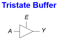
Tristate Buffer Symbol and Bus Architecture
Tristate Buffer Truth Table
| Enable () | Input () | Output () | State Description |
|---|---|---|---|
| High Impedance (Disconnected) | |||
| High Impedance (Disconnected) | |||
| Driven Low | |||
| Driven High |
Multiplexers (Mux)
A Multiplexer selects one of data inputs and routes it to a single output using select control lines.
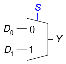
2:1 Multiplexer Block Diagram and Internal Logic
2:1 Multiplexer
- Inputs: Data , Select
- Boolean Equation:
2:1 Mux Truth Table & State Mapping
| Select () | Input | Input | Output () |
|---|---|---|---|
General Multiplexer Equations
For a Mux with select lines, the output is the sum of products of each minterm (formed by the select lines) and its corresponding data input :
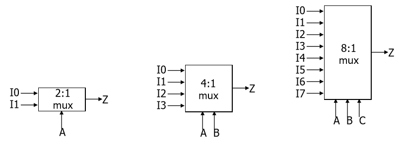
General Minterm-based Multiplexer Structure
4:1 Multiplexer (, Selects )
8:1 Multiplexer (, Selects )
Multiplexers as General-Purpose Logic Generators
A Mux can implement any -variable Boolean function by connecting variables to the select lines and driving the data inputs with , , or the remaining variable (and its complement).
Example Design Problem
Implement the 3-variable function using a 4:1 Multiplexer (Select lines connected to ).
Method 1: Plug-and-Chug (Algebraic Evaluation)
Evaluate for each fixed combination of select variables :
Method 2: K-Map Partitioning
Partition the 3-variable K-Map into sub-blocks corresponding to select states and identify the output relationship relative to variable :
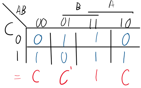
K-Map Partitioning for Mux Data Input Derivation
Demultiplexers (Demux)
A Demultiplexer performs the inverse operation of a multiplexer: it routes a single data input line to one of output lines , selected by control lines .
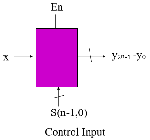
1-to-N Demultiplexer Logic Diagram
Mathematical Function Definition
Enable Line Behavior
If the enable line , all outputs remain forced to , regardless of input or select line values.