Abstract
Shifters are combinational or sequential hardware blocks used in ALUs for bit manipulation, multiplication/division by powers of 2, and field alignment. The three primary shift operations are Logical Shifts (filling vacated positions with zeros), Arithmetic Shifts (preserving signed integer values via MSB sign-extension on right shifts), and Rotators (circulating bits without signal loss). High-performance hardware implements variable-distance shifting in constant clock time using multi-stage multiplexer networks known as Barrel Shifters.
Shift and Rotate Operations
Shifting moves the binary bits of an -bit vector left or right by a specified distance .
1. Logical Shifter
- Behavior: Shifts bits left or right, padding all vacated bit positions with zeros ().
- Arithmetic Function: Unsigned multiplication by (left shift) or division by (right shift).
Worked 5-Bit Examples (Input: )
- Logical Shift Right by 2 ():
- Logical Shift Left by 2 ():
2. Arithmetic Shifter
- Behavior: Performs bitwise shifts while preserving the two’s complement sign of the number.
- Arithmetic Shift Right (): Fills vacated high-order bits with the old Most Significant Bit (MSB / sign bit).
- Arithmetic Shift Left (): Identical to logical shift left (fills low-order bits with ).
- Arithmetic Function: Signed division by (right shift) preserving negative sign bits.
Worked 5-Bit Examples (Input: , MSB = )
- Arithmetic Shift Right by 2 (): (MSB replicated twice)
- Arithmetic Shift Left by 2 ():
3. Rotator (Circular Shift)
- Behavior: Shifts bits circularly so that bits shifted off one end wrap around and enter at the opposite end. No bits are discarded.
Worked 5-Bit Examples (Input: )
- Rotate Right by 2 (): (Last two bits wrapped to front)
- Rotate Left by 2 (): (First two bits wrapped to end)
Operation Summary Table
| Operation | Symbol | Direction | Vacated Bit Fill Strategy | 5-Bit Example (, ) |
|---|---|---|---|---|
| Logical Shift Right | Right | Zeros () | ||
| Logical Shift Left | Left | Zeros () | ||
| Arithmetic Shift Right | Right | Sign Bit (Original MSB ) | ||
| Arithmetic Shift Left | Left | Zeros () | ||
| Rotate Right | Right | Wrapped Low-Order Bits | ||
| Rotate Left | Left | Wrapped High-Order Bits |
General Shifter Hardware Architecture (Barrel Shifter)
Naive single-bit iterative shifters require clock cycles to shift by bits. A Barrel Shifter executes arbitrary -bit shifts in a single combinational delay pass using a crossbar matrix or a logarithmic cascade of multiplexers.
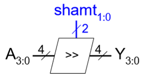
High-Level General Shifter Block Schematic
Logarithmic Multiplexer Array Design
For an -bit shifter supporting shifts from to positions, the design uses sequential stages of multiplexers:
- Stage 0 (): Shifts by bit or bits.
- Stage 1 (): Shifts by bits or bits.
- Stage 2 (): Shifts by bits or bits.
- Stage (): Shifts by bits or bits.
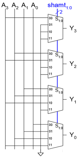
4-Bit Barrel Shifter Array Implementation using 2:1 Multiplexers
Advantages of Logarithmic Barrel Shifters
- Propagation Delay: Grows logarithmically as gate levels rather than linearly .
- Control Simplicity: The shift amount in binary () directly drives the select lines of each multiplexer stage.