Abstract
High-Level State Machines (HLSMs) extend classical Finite State Machines by integrating multi-bit datapath elements—such as local storage registers, arithmetic operations, and relational comparators—directly into state transition definitions. While classical FSMs suffer from exponential state explosion when handling multi-bit data, HLSMs separate control logic from data manipulation. This allows complex algorithms, multi-bit processing, and continuous accumulation to be specified concisely before hardware synthesis.
Motivation: Limits of Classical FSMs
In classical FSMs, every unique combination of multi-bit data requires a distinct control state. Representing even modest -bit numbers ( possible values) causes state explosion, making visual state diagrams and state tables unmanageable.
Example: Soda Dispenser Controller
Consider a automated soda dispenser with the following system interface:
c(1-bit input): Asserts'1'when a coin is deposited.a(8-bit input): Binary value representing the value of the deposited coin.s(8-bit input): Binary value representing the cost of the soda.d(1-bit output): Asserts'1'to dispense soda when total deposited value .
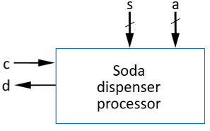
Soda Dispenser High-Level Interface
The Design Challenge
To implement this using a classical FSM, distinct states would be required for every possible accumulated money total (). An HLSM resolves this by introducing local storage variables (registers) to track totals dynamically across clock cycles.
Core Extensions of HLSMs
HLSMs bridge pure control logic (FSMs) and computational datapaths by introducing three fundamental extensions:
- Multi-Bit Inputs and Outputs: Supports -bit data buses (, ) rather than requiring individual single-bit control wires.
- Local Storage (Registers): Internal variables retain multi-bit state data across clock cycles without creating separate control states.
- Arithmetic & Relational Operations: Allows conditional transitions and state actions to evaluate math expressions (, , ) and relational comparisons (, , ).
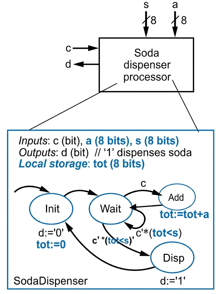
HLSM State Diagram for Soda Dispenser Controller
HLSM Syntax & Modeling Conventions
To prevent ambiguity during hardware synthesis, HLSM specifications adhere to strict notation rules:
| Category | Syntax Rule | Example | Description |
|---|---|---|---|
| Single-Bit Literals | Single Quotes | '0', '1' | Represents single binary control signals. |
| Integers / Decimals | No Quotes | 0, 15, 250 | Numerical values used in arithmetic/comparisons. |
| Multi-Bit Vectors | Double Quotes | "00", "1101" | Fixed bit-pattern assignments for data buses. |
| Equality Comparison | == | tot == s | Evaluates true if multi-bit values match. |
| Multi-Bit Output | Registered | out_reg | Multi-bit outputs must be held in local storage. |
| Comments | // | // Clear total | Precedes explanatory notes in state blocks. |
Architectural Comparison: FSM vs. HLSM
Both FSMs and HLSMs are synchronous sequential networks where transitions occur strictly on active clock edges. However, their internal abstraction boundaries differ significantly:
| Feature | Classical FSM | High-Level State Machine (HLSM) |
|---|---|---|
| Primary Focus | Low-level control logic sequencing. | Combined control and datapath behavior. |
| Multi-Bit Data Storage | Not supported (only encodes binary state ). | Supported via internal multi-bit registers. |
| State Count | Grows exponentially with data range (). | Minimal (states represent execution steps, not data values). |
| Transition Conditions | Simple Boolean logic functions (). | Complex expressions (, ). |
| Hardware Mapping | Maps directly to Flip-Flops + Gates. | Synthesizes into a Control Unit + Datapath (ALUs, Registers, Muxes). |