Abstract
Finite State Machines (FSMs) provide the core architectural paradigm for designing complex sequential controllers. Unlike purely combinational logic, sequential networks incorporate state-storing memory elements (Flip-Flops) and feedback paths to track historical state. FSM architectures fall into two primary classes: Moore Machines (where outputs depend strictly on the current state) and Mealy Machines (where outputs depend on both current state and present inputs). Designing an FSM follows a systematic 5-step synthesis pipeline—from state diagram conceptualization to K-map logic minimization.
Circuit Specifications: Combinational vs. Sequential
Digital circuits are broadly classified into Combinational Networks (memoryless) and Sequential Networks (state-dependent).
| Specification Method | Combinational Networks | Sequential Networks |
|---|---|---|
| Primary Representation | Truth Tables | State Transition Diagrams |
| Logic Equations | Boolean Algebraic Equations | Characteristic Equations & Excitation Equations |
| Structural Modeling | Logic Gate Diagrams (Strictly Acyclic / No Feedback) | Logic Diagrams (Flip-Flops + Cyclic Feedback Loops) |
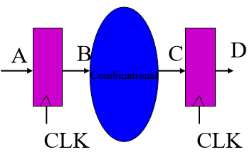
Combinational Circuit Model (No Feedback)
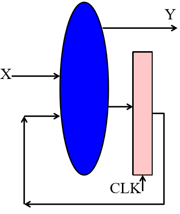
Sequential Circuit Model (Flip-Flop Memory + Feedback Loop)
2-Bit Counter Synthesis Example
A 2-bit counter cycles through binary states on consecutive clock pulses.
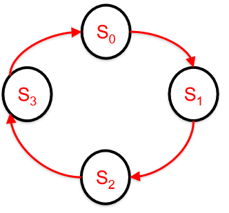
State Diagram for a 2-Bit Synchronous Counter
State Transition Table
| Current State () | Next State () | Current State Bits () | Next State Bits () |
|---|---|---|---|
D Flip-Flop Excitation Logic
Using D Flip-Flops, the excitation inputs and must match the target next-state outputs and :
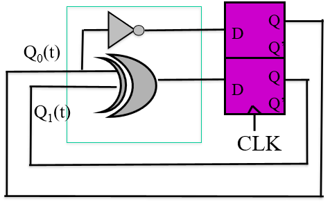
Circuit Implementation of 2-Bit Counter using D Flip-Flops
Key Sequential Intuition
When working with Flip-Flops, the outputs () represent the Current State, whereas the inputs () represent the computed Next State that will be loaded on the subsequent clock edge.
Finite State Machine (FSM) Foundations
An FSM is a formal mathematical model of computation consisting of:
- A finite set of States ().
- A set of Inputs () and Outputs ().
- A designated Initial State ().
- A set of State Transitions governed by input conditions.
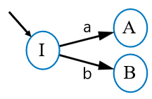
Generic Finite State Machine Conceptual Framework
Deterministic Transition Rules
- For input variables, exactly outgoing transitions exist for each state.
- Exclusivity: Exactly one transition condition can evaluate to TRUE at any given clock cycle.
Mealy vs. Moore Machines
Comparison Matrix
| Property | Mealy Machine | Moore Machine |
|---|---|---|
| Block Diagram | 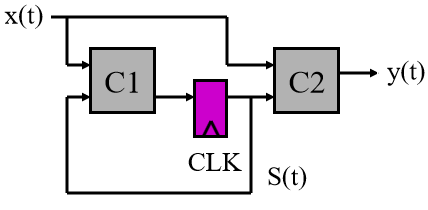 | 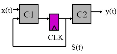 |
| State Diagram | 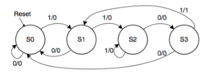 | 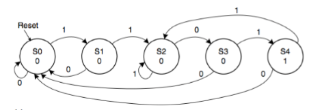 |
| Output Equation | ||
| Next-State Equation | ||
| Output Dependency | Functions of both Current State and Present Input. | Functions strictly of Current State. |
| Output Timing Response | Outputs react immediately to input changes within the cycle (susceptible to input glitches). | Outputs change only on the active clock edge when state updates. |
| State Count | Often requires fewer states than an equivalent Moore machine. | May require more states to decode identical sequence logic. |
Systematic 5-Step FSM Design Procedure
Synthesizing a functional FSM from a behavioral specification follows a structured 5-step pipeline:
flowchart TD
    A["Problem Description"] --> B["Step 1: State Diagram"]
    B --> C["Step 2: State Table & Binary Assignment"]
    C --> D["Step 3: Excitation Table"]
    D --> E["Step 4: K-Map Minimization"]
    E --> F["Step 5: Gate-Level Circuit Construction"]
- State Diagram Construction: Draw a high-level Mealy or Moore state diagram representing all valid operating modes and transitions.
- State Table & Binary State Assignment: Construct a state table mapping . Assign binary state codes to symbolic states (e.g., ).
- Excitation Table Generation: Expand the binary state table into an excitation truth table detailing flip-flop input signals () and circuit outputs () for every input/state combination.
- K-Map Logic Minimization: Construct Karnaugh Maps for every next-state bit and circuit output line to derive minimal Sum-of-Products (SOP) expressions.
- Circuit Implementation: Draw the final logic gate schematic, connecting combinational excitation logic to the data inputs of state flip-flops.