Abstract
An Arithmetic Logic Unit (ALU) is the central combinational processing core of a CPU processor, executing arithmetic operations (addition, subtraction) and logical operations (bitwise AND, OR) on multi-bit operands. Modern processor architectures—such as MIPS or RISC-V—construct wide -bit ALUs hierarchically by cascading identical 1-bit ALU primitives. Operating in parallel for bitwise logic and in series for carry propagation, a centralized
ALUopcontrol line selects which operation output passes through a multiplexer to the final result bus.
Top-Level ALU Interface & Signals
At the system level (e.g., MIPS architecture), the ALU accepts two multi-bit data inputs ( and ), a multi-bit control opcode (ALUop or Operation), and outputs the computed result along with status flag signals.
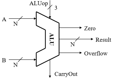
Top-Level MIPS-Style ALU Block Symbol
Port Description
- Data Inputs (): -bit operands supplied from processor registers or immediate values.
- Operation Select (
ALUop): -bit control code generated by the CPU Control Unit indicating the exact operation to execute. - Output Result: -bit computed output value.
- Status Flags: Optional outputs indicating hardware conditions (e.g., , , ).
1-Bit ALU Building Block
A multi-bit ALU is built by designing a single-bit slice capable of operating on 1-bit inputs and .
Internal Components of a 1-Bit Slice
- AND Gate: Computes bitwise .
- OR Gate: Computes bitwise .
- Full Adder: Computes arithmetic sum , producing and .
- Operation Multiplexer: A 3:1 (or 4:1) multiplexer controlled by
ALUopto route the desired operation to the output.
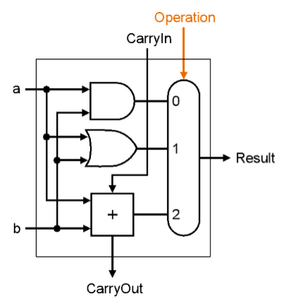
Internal Logic Schematic of a 1-Bit ALU Cell
1-Bit ALU Control Decoding Table
ALUop Code | Selected Multiplexer Input | Executed Operation | Output Function () |
|---|---|---|---|
| 00 | Input 0 | Bitwise AND | |
| 01 | Input 1 | Bitwise OR | |
| 10 | Input 2 | Addition (ADD) |
Constructing a 32-Bit Modular ALU Architecture
To process 32-bit operands, 32 individual 1-bit ALUs are arrayed together.
- Bitwise Parallelism: Logical operations (AND, OR) execute independently across all 32 slices in parallel.
- Carry Propagation Chain: For addition, carry signals flow sequentially from least significant bit () to most significant bit (), where connects directly to .
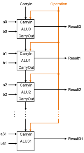
32-Bit ALU Architecture Cascading 32 1-Bit ALU Cells
Signal Interconnections Across Slices
- Bit Slices : Each cell receives operand bits and , producing .
- Centralized Control (
ALUop): The sameALUopcontrol lines are broadcast to the operation multiplexer of every 1-bit slice simultaneously. - Carry Chain:
- provides the initial carry input to .
- for .
- yields the final overall carry flag for the 32-bit operation.
Extending the ALU (Subtract & Comparisons)
By adding minimal control logic to the basic 1-bit ALU primitive, the full CPU ALU expands functionality to support:
- Subtraction (): Invert bits (via a 2:1 Mux with a signal) and set initial to execute .
- Set Less Than (SLT): Uses subtraction sign-bit evaluation () to output if , otherwise .
- Zero Flag (): NORs all 32 result bits together () to signal branch conditions when .