Abstract
Register-Transfer Level (RTL) Synthesis translates high-level behavioral models (such as software algorithms or High-Level State Machines) into structural hardware composed of a Datapath and a Controller. The datapath executes data operations using registers, adders, multiplexers, and comparators, while the controller (a classical FSM) manages the datapath via control signals based on status feedback and external inputs. The entire system’s maximum operational clock frequency () is bounded by the worst-case register-to-register critical path delay spanning the datapath, controller, and their interconnecting interface.
The Official RTL Design Process
Converting a high-level system behavioral specification into digital hardware follows a structured 2-phase, 5-step synthesis methodology:
flowchart LR
    A["System Behavior"] --> B["Step 1: Capture HLSM"]
    B --> C["Step 2: Convert to Circuit"]

    C --> D["Step 2A: Create Datapath"]
    C --> E["Step 2B: Connect Controller"]
    C --> F["Step 2C: Derive Controller FSM"]
    C --> G["Step 2D: Finalize Circuit"]
Synthesis Step Summary
| Step | Phase / Sub-step | Description |
|---|---|---|
| Step 1 | Capture Behavior | Describe desired system behavior as a High-Level State Machine (HLSM) using states, transitions, multi-bit variables, and complex arithmetic expressions. |
| Step 2A | Create Datapath | Instantiate storage elements (registers) and functional units (adders, comparators, shifters) to perform all multi-bit data operations defined in the HLSM. |
| Step 2B | Connect Controller | Map external control inputs/outputs and datapath status signals to a centralized controller block. Routing load/clear signals to datapath registers. |
| Step 2C | Derive Controller FSM | Convert the HLSM into a classical Finite State Machine (FSM) by replacing all data operations with explicit control assertions and status inputs. |
| Step 2D | Finalize Circuit | Synthesize the controller FSM into state registers and combinational excitation logic. |
Walkthrough: Soda Dispenser RTL Synthesis
Info
For the problem statement of the Soda Dispenser Example, visit Example Soda Dispenser Controller
Step 1: HLSM Behavior Capture
The soda dispenser continuously checks for coin deposits (c), updates an accumulated total sum (tot = tot + a), compares tot against the soda cost (s), and asserts the dispense signal (d = '1') when tot >= s.
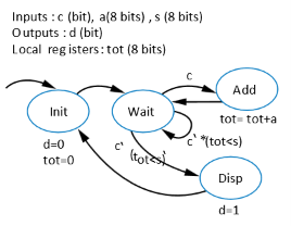
HLSM for Soda Dispenser Controller
Step 2A: Building the Datapath
To support the HLSM’s data operations, the datapath requires:
- Register (
tot): An 8-bit register to store accumulated coin values over time (withtot_ldandtot_clrcontrol lines). - Adder (8-Bit): To compute
tot + a. - Comparator (8-Bit): To evaluate (generating status output
tot_lt_s).
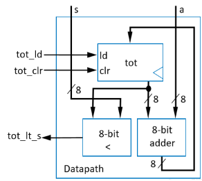
Soda Dispenser Datapath Hardware Schematic
Step 2B & 2C: Controller Interface & FSM Derivation
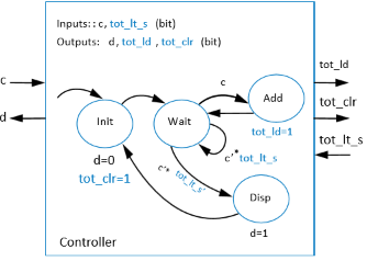
The controller manages the datapath using status feedback (tot_lt_s) and external control (c), issuing load (tot_ld), clear (tot_clr), and dispense (d) signals.
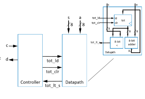
Integrated Datapath-Controller Interface
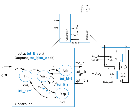
Derived Controller FSM (Data Operations Replaced with Control Signals)
Step 2D: Controller Excitation Table
The derived FSM maps directly to a classical excitation truth table for logic gate synthesis:
| Current State () | Coin Detected () | Sum Less Than Cost (tot_lt_s) | Next State () | Dispense () | Register Load (tot_ld) | Register Clear (tot_clr) |
|---|---|---|---|---|---|---|
| Init () | ||||||
| Init () | ||||||
| Wait () | ||||||
| Wait () | ||||||
| Add () | ||||||
| Add () | ||||||
| Disp () |
Final Hardware Logic Gate Implementation
RTL Timing & Critical Path Delay
In RTL design, system operating frequency () is strictly constrained by the longest register-to-register path (Critical Path).
flowchart LR
    Reg1["<b>Launching Register</b>"] -->|"Path A: Inside Datapath"| Logic1["<b>ALU / Adders</b>"]
    Logic1 -->|"Path B: Datapath to Controller"| Controller["<b>FSM Logic</b>"]
    Controller -->|"Path C: Inside Controller"| Reg2["<b>Receiving Register</b>"]
Critical Path Locations
- Inside the Datapath: Delays through wide arithmetic structures (e.g., array multipliers, long adder chains).
- Inside the Controller: Delays through complex next-state excitation logic.
- Across Datapath-Controller Boundaries: Status signal evaluation delays feeding into controller decision logic.
Sequential Timing Governing Equations
To prevent timing violations across hundreds or thousands of internal RTL paths, all register-to-register paths must satisfy:
Behavioral Synthesis: C Code to Gates
High-Level Synthesis (HLS) automated tools compile behavioral software algorithms directly into HLSM state machines.
Example: Sum of Absolute Differences (SAD)
int SAD(byte A[256], byte B[256]) {
    uint sum;
    short uint i;
    sum = 0;
    i = 0;
    while (i < 256) {
        sum = sum + abs(A[i] - B[i]);
        i = i + 1;
    }
    return sum;
}
Construct to HLSM State Translation Rules
| Control Construct | C Code Pattern | Synthesized HLSM State Structure |
|---|---|---|
| Assignment Statement | sum = 0; | Converts into a single execution state containing the variable assignment.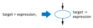 |
| If-Then Statement | if (cond) { ... } | Converts into a decision state evaluating cond. If true, transitions to “Then” state sequence; if false, branches directly to exit.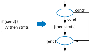 |
| If-Then-Else | if (cond) { A } else { B } | Converts into a decision state branching to two distinct state pathways before re-converging.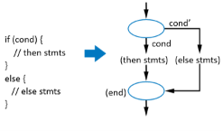 |
| While Loop | while (cond) { ... } | Converts into a loop-head decision state. If true, executes loop body states and loops back; if false, exits.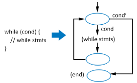 |
Dedicated Hardware Circuit vs. Microprocessor Execution
Comparing the performance of the Sum of Absolute Differences (SAD) algorithm on a custom synthesized RTL circuit versus execution on a general-purpose microprocessor highlights the architectural efficiency of application-specific hardware.
Execution Performance Breakdown
- Custom Dedicated Circuit:
- Executes each loop iteration across 2 dedicated states ( and ).
- Requires clock cycles per array item:
- General-Purpose Microprocessor:
- For each iteration (), the processor must fetch memory values into local registers, compute the difference, calculate absolute value, update the sum accumulator, and increment the loop counter.
- Requires approximately clock cycles per array item:
| Architecture | Execution Strategy | Cycles / Iteration | Total Execution Cycles | Relative Performance |
|---|---|---|---|---|
| Microprocessor | Sequential Software Instructions | (Baseline) | ||
| Custom RTL Circuit | Dedicated Hardware Datapath | Faster (300%) |
Hardware Parallelism Potential
While a sequential RTL implementation is faster than a microprocessor, hardware throughput can be scaled further by leveraging parallelism—such as unrolling loops and processing multiple array elements simultaneously via parallel adder/subtractor trees.