Abstract
Adders and Subtractors form the fundamental arithmetic engine of an Arithmetic Logic Unit (ALU). Basic 1-bit primitives—the Half Adder and Full Adder—can be cascaded into multi-bit architectures such as the linear Ripple-Carry Adder (RCA) or the high-speed Carry-Lookahead Adder (CLA), which eliminates carry-propagation bottlenecking using Generate () and Propagate () logic. By leveraging Two’s Complement arithmetic, subtraction is executed as addition (), enabling unified, hardware-efficient Adder-Subtractor circuits with built-in overflow detection.
1-Bit Adder Building Blocks
Half Adder
A Half Adder adds two 1-bit inputs () and produces a Sum () and Carry-out (). It cannot accept an incoming carry from a less significant bit position.
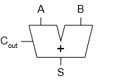
Half Adder Block Schematic
Half Adder Truth Table & Logic Equations
Full Adder
A Full Adder adds three 1-bit inputs: two operands () and an incoming Carry-in ().
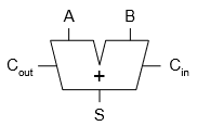
Full Adder Circuit Diagram
Full Adder Truth Table & Logic Equations
Multi-Bit Adders & Propagation Delay
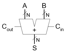
Multi-Bit Adder Symbol
Ripple-Carry Adder (RCA)
A Ripple-Carry Adder chains 1-bit Full Adders in series, passing from bit position directly into of bit position .
4-Bit Ripple-Carry Adder Chain
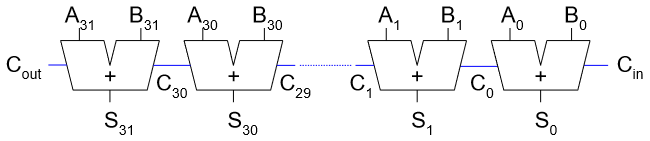
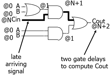
Carry Signal Ripple Delay Path
Propagation Delay Bottleneck
The worst-case propagation delay occurs when a carry generated at the least significant bit () ripples through every stage to the most significant bit (). For an -bit adder with Full Adder delay :
Carry-Lookahead Adder (CLA)
A Carry-Lookahead Adder speeds up addition by calculating carry signals in parallel using Generate () and Propagate () signals, avoiding sequential bit-by-bit carry ripple.
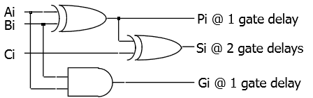
Carry-Lookahead Adder Architecture
Generate & Propagate Definitions
For any bit stage :
- Generate (): A carry is generated internally regardless of .
- Propagate (): An incoming carry will propagate to .
The next carry is computed as:
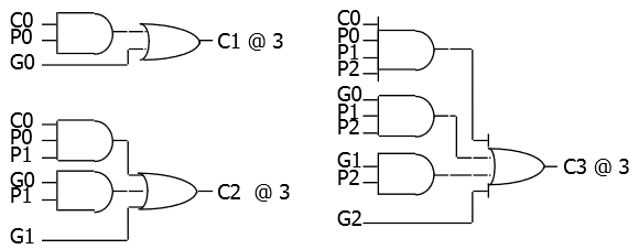
Unrolled Carry Lookahead Logic
Unrolled Carry Equations
Expanding the recursive carry relation eliminates intermediate carry dependencies:
Block Propagate and Generate (-bit Blocks)
To construct wider adders hierarchically without massive fan-in gates, individual stages are grouped into -bit blocks (e.g., 4-bit blocks):
Two’s Complement Arithmetic & Subtraction
In fixed-width binary systems, two’s complement notation converts subtraction into an addition operation:
Two’s Complement Negation Procedure ()
To negate a binary number :
- Take the bitwise complement ().
- Add .
- Example (+7 to -7 in 4 bits):
- Example (-7 to +7 in 4 bits):
Worked Subtraction Example ()
Arithmetic Overflow Detection
Overflow occurs when an arithmetic operation produces a result that exceeds the representable range of the fixed -bit container.
Method 1: Sign Bit Anomaly Detection
Overflow occurs if and only if two numbers with the same sign are added, but produce a result with a different sign. Adding a positive and a negative number can never result in overflow.
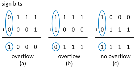
Overflow Circuit based on Sign-Bit Comparison
Method 2: Carry-In vs. Carry-Out XOR
A simpler hardware implementation detects overflow by taking the XOR of the carry into the sign bit () and the carry out of the sign bit ():
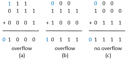
Simplified Overflow Detection Circuit using at MSB
| (Carry Into MSB) | (Carry Out of MSB) | Overflow () | Condition Description |
|---|---|---|---|
| No Overflow | |||
| Negative Overflow (Sum wrapped into positive range) | |||
| Positive Overflow (Sum wrapped into negative range) | |||
| No Overflow |
Configurable Adder-Subtractor Circuit
By combining bitwise XOR gates with a multi-bit adder, a single circuit can perform both addition and subtraction governed by a select control signal ( / ).
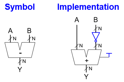
Bitwise Conditional Inversion using XOR Gates
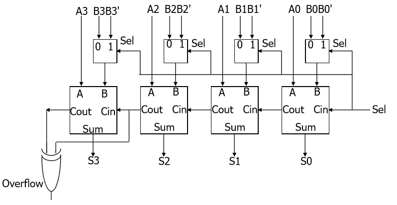
Integrated -Bit Adder-Subtractor Circuit with Overflow Output
Operational Modes
-
Addition Mode ():
- XOR gates pass unchanged ().
- Carry-in .
- Output: .
-
Subtraction Mode ():
- XOR gates invert ().
- Carry-in .
- Output: .